Legal Notice
Introduction
Circuit Description
Schematic
Construction
Wire-Wrap® Board Lay-out Drawing
Wire-Wrap® Board Images
Parts Table
Test and Calibration Procedure
Images


The 2006 Minimum Theremin
(Updated December 21, 2006)
Contents:
Legal Notice
Introduction
Circuit Description
Schematic
Construction
Wire-Wrap® Board Lay-out Drawing
Wire-Wrap® Board
Images
Parts Table
Test and Calibration Procedure
Images
Legal Notice
(back to contents)
Information contained in this document ©2006 by Arthur Harrison. It may not be reproduced in any form without his permission, and shall acknowledge him as the copyright holder and author.
Unless specifically stated in a written contract, Arthur Harrison grants no licence or permission to any party for the use of the information contained in this document for the manufacture and sale of goods, nor any other commercial utilization. Refer licensing inquiries to: theremin1@worldnet.att.net.
Arthur Harrison assumes no liability for any damages, direct, or consequential, which may arise from the dissemination, application, or misapplication of the content contained in this site. The User of the information provided in this site assumes all responsibility for any damages, direct or consequential, which may arise from its use. Arthur Harrison retains the right to alter the content within this site at any time without notice.
Introduction
(back to contents)
I designed the "Minimum Theremin" with the objectives of simplicity and economy, and in response to frequent requests for an instrument that can be built with readily-available parts. This is a pitch-only instrument that demonstrates the basic theremin concept, perfect for science fair projects or as a coffee table conversation piece. Although it doesn't have the qualities of more expensive and complex theremins, it is very inexpensive, relatively easy to make, and sufficiently sensitive and stable for playing a melody. A suggested lay-out is included for perforated-board construction, however, any number of alternative methods may be used to build the Minimum Theremin.
The 2006 version of the Minimum Theremin, described here, supersedes an earlier version described in the original, 1999 article. This version contains changes that permit the use of U1 and U2 integrated circuits from a wider variety of manufacturers. Builders of the original Minimum Theremin may easily update their circuit to the latest version. Click here for instructions.
Two identical, commonly-available integrated circuits known as "hex inverters"
are used for the theremin's primary functions. These are CMOS (Complimentary
Symmetry Metal Oxide Semiconductor) devices, typically used in digital circuits
to perform a logic function called "inversion." Each IC contains six identical
sections; thus the term "hex inverter."
U1 sections A and B form the theremin's variable oscillator that operates in a frequency range around 73kHz. The antenna forms one-half of a variable capacitor that is part of this oscillator's frequency-determining network, and the player's hand forms the other half. As the distance between the hand and the antenna varies, so does the capacitance and therefore the oscillator's frequency. U1 section C buffers the variable oscillator's output to provide impedance isolation from the rest of the circuit.
U2 sections A and B comprise the theremin's local oscillator that is adjusted with PITCH NULL potentiometer RV2 and PITCH NULL CALIBRATION potentiometer RV1. RV1 is a miniature "trimmer" type, mounted on the circuit board, used to calibrate the local oscillator's frequency range. With RV1 properly adjusted, the local oscillator's frequency will equal the variable oscillator's frequency with the hand furthest away from the antenna. Under these conditions, the phase relationship of the two oscillators will be constant due to their small, but finite capacitive coupling, so no audible tone will be produced.
The inverters' propagation delays and output impedances are supply-dependent. Accordingly, PITCH NULL potentiometer RV2 affects the local oscillator's frequency by varying its supply voltage. This method of adjustment permits RV2 to be located at any convenient distance from the circuit and antenna, since frequency variations resulting from stray capacitance between the potentiometer's slider and ground are decoupled by capacitor C8. In use, RV2 is adjusted by the player so that the theremin is silent with the hand furthest away from the antenna, and produces the lowest tone when the hand is at the maximum playing distance. U2 section C buffers the variable oscillator's output to provide impedance isolation from the rest of the circuit. The three remaining U2 sections are not used, so their inputs are grounded.
Diodes CR2 and CR3, and resistor R3 comprise a logic "OR" gate which is the theremin's mixer. The mixer "heterodynes" the two oscillator signals, producing sum and difference terms of their fundamental frequencies and harmonics. U1 section F buffers the mixer's output. C4 is a DC blocking capacitor that couples the mixed signal to a low-pass filter consisting of R4 and C5. This filter reduces the inaudible heterodyne sum products, leaving the audible difference, or "beat frequency" product. The beat frequency signal is applied to an amplifier comprised of U1 sections D and E, and gain-determining resistors R5 and R6. Capacitor C6 provides a second low-pass filtering section to further attenuate the inaudible heterodyne products.
The following figures of the logic "OR" gate and related waveforms illustrate the mixer operation. A 64kHz squarewave from the variable oscillator is applied to input "A", and a 76kHz squarewave from the local oscillator is applied to input "B." Waveform "C" is the mixer's output. In this example, the frequency of each input waveform is above the hearing range, but the output waveform is a pulse train containing an audible frequency related to their difference. This is evident in the periodicy of waveform "C's" pulse clusters, that for this example of frequency inputs, appear at an audible beat frequency of 12kHz.
Since the theremin's oscillators have some sensitivity to power supply variations, VR1, a low-dropout voltage regulator IC, is used to furnish a steady 5V to the circuit. The circuit uses less than 2mA of current, so a nine-volt alkaline battery will provide many days of operation. Rectifier CR1 protects the circuit from accidental battery reversal, and R12 prevents excessive current from causing CR1 and the battery to heat under such a condition. Since the circuit draws less than 2mA, the voltage drop across R12 is less than 200mV, causing a relatively insignificant loss in battery life. The instrument will operate with a battery as low as 5.5V.
In the prototype, the output at J1 is 2.75V peak-to-peak at 100Hz, decreasing to about 450mV peak-to-peak at 1000Hz. The theremin's useful pitch range is about 200Hz to 1600Hz, or three octaves, for a corresponding hand distance of about eighteen inches to one inch from the plate antenna. The inherently low "Q" characteristic of the oscillators establish a limit for the lower audible frequency, below which, electromagnetic interference from 60Hz power lines and appliances, combined with stray-capacitive coupling between the oscillators, compromise the output fidelity. These conditions improve if the instrument is far from interfering sources. The values of the oscillators' frequency-determining components may be adjusted empirically to obtain the best compromise of sensing range and fidelity. For example, as C3 is increased, interference effects will diminish at the expense of decreased sensing range.
Regarding the difference between this version of the Minimum Theremin and the earlier version: This version's mixer, comprised of a diode "OR" gate followed by a buffer, produces a heterodyne signal that is a full-amplitude (zero to +5V) pulse train with fast transitions, resulting in a tone quality which has a greater proportion of harmonics, and a well-defined output amplitude. The earlier version utilizes an uncharacterized CMOS inverter parameter that varies from one IC to another, generally producing a more fundamental tone, but not as consistent in amplitude nor harmonic content.
The Minimum Theremin may be connected to an amplifier via mono OUTPUT jack J1. It also has sufficient output power to drive efficient, high-fidelity headphones. For use with stereo headphones, the user may wish to replace J1 with a stereo type that has its "tip" and "ring" contacts connected together.
NOTICE: Do not play this instrument at a high volume, especially when using headphones. Use headphones that have a built-in volume control, and adjust the volume control for a comfortable level. Hearing experts advise against the continuous, extended use of headphones.
For a theremin to operate properly, sufficient capacitive coupling must exist
between the player's body and the instrument. Although not obvious, a player
is sufficiently "coupled" to earth via his or her surface area, which presents
a large capacitance to earth's ground through "free space." When the theremin
is connected to an amplifier, it too, is grounded via an electrical connection
and/or capacitance between the amplifier circuitry and earth. This "free
space" coupling, along with the amplifier's connection to ground, provide
the desired common connection between the player's body and the instrument.
When used with headphones and not connected to external equipment, there
may not be sufficient capacitive coupling between the instrument and player.
This may be remedied by connecting the circuit's ground (battery negative
terminal) to earth or a nearby metal object. A metal microphone stand, when
used to mount the theremin, is suitable for this purpose. If this is not
practical, grasping a few coils the headphone cord will provide sufficient
coupling between the player and the circuit's ground.
Temperature performance is quite excellent for this theremin; warm-up drift is negligible due to the conservative power levels in the oscillator ICs, as well as first-order drift cancellation between the identically-configured oscillator circuits.
2006 Minimum Theremin Schematic
(back
to contents)
|
Construction
(back to contents)
A kit of the major components for building a 2006 Minimum Theremin is available from Harrison Instruments, Inc. The kit includes a blank printed circuit board which greatly eases construction. Click here for ordering information.
If you prefer to construct the 2006 Minimum Theremin without the printed circuit kit, continue reading this page.
The lay-out drawing and images below illustrate the circuit board as implemented
in the prototype. The construction method utilizes perforated board (Vector
64P44WE, cut to a size of 2.9" x 4.1"), and push-in terminals (Vector T68).
The T68 terminals have a fork to accommodate component leads on the top of
the board, and 3-level Wire-Wrap® posts to accommodate Wire-Wrap®
connections on the bottom of the board. (Note: The lay-out drawing is a
simplified representation that depicts both the component and wire locations
on the same plane.)
Use 26 gauge, Kynar® insulated Wire-Wrap® wire. If Wire-Wrap®
tools are not available, 26 gauge, solid, Teflon® insulated wire may
be soldered point-to-point instead. Or, more conveniently, uninsulated 26
gauge solid ("bus") wire may be used with 26 gauge Teflon® insulation
sleeving added separately. Teflon® insulation is highly desirable, since
it will not melt with normal soldering temperatures.
To ensure low impedance, flat braid is used for the ground bus, located on
the component side of the board. The bus is made of the braid material normally
used for desoldering. Note that the braid is placed against several of the
vertically-oriented terminals and held in place with a thin seam of solder.
When this technique is used, inspect each connection carefully to ensure
that the braid is securely bonded to each terminal. For best results, the
braid material should be thoroughly "tinned" (solder coated) prior to use.
Note that trimmer potentiometer RV1 is furnished with three short wire leads.
To mount RV1, gently bend each lead 180 degrees, so that they are each parallel
to the part's housing. Then, nest the part between the three vertically-oriented
terminals as shown in the lay-out, and solder each of the leads between the
two tines of their respective terminals.
If you choose an alternative lay-out, maximize the distance between the U1 and U2 circuits to minimize their mutual capacitance. Since the impedances in this circuit are high and therefore affected by electromagnetic interference, the connections between the ICs and their associated components should be kept as direct as possible; avoid excessive wire lengths between the terminals.
With regard to component selection, U1 and U2 should be from the same manufacturer and production lot. This will help ensure that they will have similar oscillation frequencies. Several manufactures make integrated circuits suitable for the U1 and U2 positions. The following types will work:
Manufacturer |
Part Number |
On Semiconductor |
MC14069UBCP |
Texas Instruments |
CD4069UBE |
Fairchild Semiconductor |
CD4069UBCN |
ST Microelectronics |
HCF4069UBEY |
Toshiba |
TC4069UBP |
ICs including the designation "74_04," "HC," "HCT," "AHCT," "AC," or "ACT"
in their part number should be avoided in this circuit.
All the resistors are 1/4 watt, ±5 per-cent tolerance, carbon-film types. ±1 per-cent metal-film types with the nearest equivalent values may be substituted. None of the capacitors are critical with the exception of C3 and C9, which should be temperature-stable mica types with a ±5 per-cent tolerance. Viable substitutes for C3 and C9 include polystyrene or NPO ceramic types.
A note about soldering: The suggested lay-out requires considerable soldering skills due to the compact arrangement. Novices should practice their soldering with T-68 terminals, inexpensive components (such as resistors), and a separate piece of perforated board prior to building the theremin. In particular, be careful not to let a solder "bridge" form in the tiny gap between adjacent terminals, such as the terminals for R5, R6, and C6.
The circuit board has a hole in each corner for 4-40 threaded standoffs, used to mount the assembly in an enclosure such as the Keystone type 764 plastic box in the parts list. Orient the circuit board so that the adjustment screw on RV1 can be conveniently accessed through a hole in the box. Arrange the remaining items so that the battery is easily accessible, and the POWER SWITCH, OUTPUT JACK, and PITCH NULL potentiometer are mounted in logical positions.
There are no restrictions regarding the type of enclosure material, however, for a metal enclosure, route the antenna wire away from surfaces, pass the antenna wire through a hole fitted with a small rubber grommet, and attach the antenna to the enclosure with an insulated support such as the wood post in the Parts Table. In any case, the antenna should be mounted at least eight inches away from the enclosure to prevent unwanted coupling between it and other parts of the circuit.
If the theremin is equipped with an internal amplifier, enclosed in a wood cabinet, and not grounded via external equipment, the effects of electromagnetic interference may be reduced with a simple ground plane. The plane may be made of any conductive material such as copper-clad circuit board or aluminum foil. Its exact dimensions are not critical, although it should have an area ranging in size from that of the of circuit board, and up to that of the antenna. It is usually most convenient to mount the ground plane below the circuit board, using the same mounting hardware that secures the board. Connect the ground plane to any ground point on the circuit board with a short length of wire. The ground plane's role in reducing interference effects is a result of the common-mode cancellation it provides to the circuit ground with reference to the antenna, and not a result of its shielding properties. However, when mounted beneath the circuit board, such a plane will also be a benefit in reducing the coupling between the U1 and U2 oscillators.
Although 1/16th inch-thick aluminum is indicated for the antenna, any conductive material, such as aluminum foil or copper-clad circuit board, may be substituted.
See the "TEST ARRANGEMENT" drawing in the "Test and Calibration Procedure" section for a pictorial representation of the theremin's major parts and their interconnections.
2006 Minimum Theremin Board Lay-out
(back
to contents)
 |
2006 Minimum Theremin Board Images
(back
to contents)
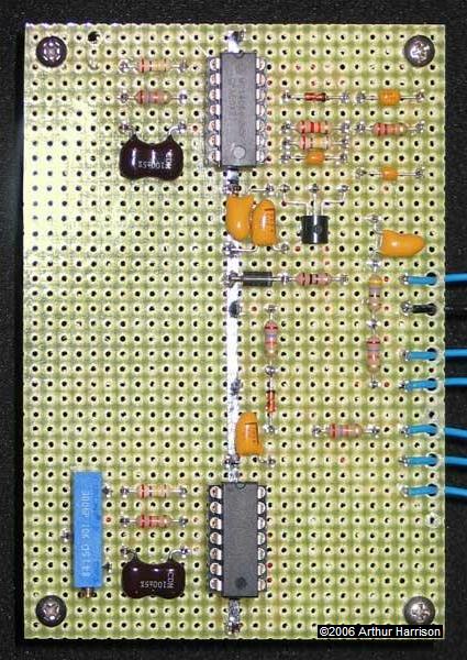
Component Side
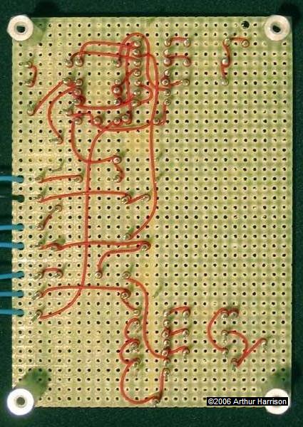
Wire Side
Parts Table
(back to contents)
Miscellaneous materials such as fasteners are excluded from this table.
Mouser |
|
Allied |
|
Digi-Key |
| ITEM | DESCRIPTION | VALUE | MANUFACTURER |
MANUFACTURER |
SUPPLIER | SUPPLIER STOCK NUMBER |
QTY |
| C1, C2, C7, C8 |
TANTALUM CAPACITOR |
10 uF +/-10%, 20 V, RADIAL |
VISHAY/ SPRAGUE |
199D106X9020C1V1E3 | MOUSER | 74-199D20V10-E3 | 4 |
| C3, C9 | MICA CAPACITOR |
100 pF, +/-5%, RADIAL |
CORNELL DUBILIER |
CD15FD101JO3 | ALLIED | 862-0008 | 2 |
| C4 | CERAMIC CAPACITOR |
0.1uF, +/-10%, 100 V, RADIAL |
VISHAY/ SPRAGUE |
1C10X7R104K100B | MOUSER | 75-1C10X7R104K100B | 1 |
| C5, C6 | CERAMIC CAPACITOR |
0.01uF, +/-10%, 100 V, RADIAL |
VISHAY/ SPRAGUE |
1C10X7R103K100B | MOUSER | 75-1C10X7R103K100B | 2 |
| CR1 | RECTIFIER | 1A, 50V, DO-41 CASE |
RECTRON | 1N4001-B | MOUSER | 583-1N4001-B | 1 |
| CR2, CR3 | DIODE | 150mA, 100V, DO-35 CASE |
VISHAY SEMICONDUCTORS |
1N4148 | MOUSER | 78-1N4148 | 2 |
| J1 | JACK (NOTE 1) |
MONO, 1/4" | SWITCHCRAFT | 11 | MOUSER | 502-11 | 1 |
| R1, R9 R6 |
RESISTOR, CARBON FILM |
270K OHM, +/-5%, 1/4 WATT |
XICON | 291-270K-RC | MOUSER | 291-270K-RC | 3 |
| R2, R3, R8, R11 |
RESISTOR, CARBON FILM |
27K OHM, +/-5%, 1/4 WATT |
XICON | 291-27K-RC | MOUSER | 291-27K-RC | 4 |
| R4, R5, R10 |
RESISTOR, CARBON FILM |
22K OHM, +/-5%, 1/4 WATT |
XICON | 291-22K-RC | MOUSER | 291-22K-RC | 3 |
| R7 | RESISTOR, CARBON FILM |
470 OHM, +/-5%, 1/4 WATT |
XICON | 291-470-RC | MOUSER | 291-470-RC | 1 |
| R12 | RESISTOR, CARBON FILM |
100 OHM, +/-5%, 1/4 WATT |
XICON | 291-100-RC | MOUSER | 291-100-RC | 1 |
| RV1 | POTENTIOMETER, TRIMMER |
10K OHM, +/-10%, 15 TURN, CERMET |
BOURNS | 3006P-1-103-LF | MOUSER | 652-3006P-1-103-LF | 1 |
| RV2 | POTENTIOMETER, PANEL |
1K OHM, +/-10%, CARBON COMPOSITION |
XICON | RV24AF-10-15R1-B1K | MOUSER | 31VA301-F | 1 |
| S1 | SWITCH | SPDT | C & K | 7101SYZQE | MOUSER | 611-7101-001 | 1 |
| U1,U2 | INTEGRATED CIRCUIT, CMOS, HEX INVERTER |
(USE PART NUMBER) |
ON SEMICONDUCTOR | MC14069UBCP | ALLIED | 568-6439 | 2 |
| VR1 | INTEGRATED CIRCUIT, LOW DROPOUT VOLTAGE REGULATOR |
5.0 VOLT, TO-92 CASE |
NATIONAL SEMICONDUCTOR |
LP2950ACZ-5.0/NOPB | ALLIED | 288-0698 | 1 |
. |
PERFORATED BOARD |
GLASS-EPOXY, 6.5" X 4.5" X 0.062" |
VECTOR | 64P44WE | MOUSER | 574-64P44WE | 1 |
. |
TERMINAL | PRESS-FIT, SOLDER FORK TO WIRE-WRAP® |
VECTOR | T68/C (=PACKAGE OF 100) |
MOUSER | 574-T68/C | 1 |
. |
SOCKET FOR U1,U2 |
14-POSITION, WIRE-WRAP® | MILL-MAX | 123-93-314-41-001000 | MOUSER | 575-293314 | 2 |
. |
WIRE, WIRE-WRAP®, RED |
26 GAUGE, KYNAR® INSULATED |
OK INDUSTRIES | R26R-010 (=ROLL OF 100') |
MOUSER | 801-R26R | 1 |
. |
WIRE, HOOKUP, BLUE |
22 GAUGE, 19 STRAND, TEFLON® INSULATED |
ALPHA | 5855 BL005 (=ROLL OF 100') |
MOUSER | 602-5855-100-06 | 1 |
. |
BRAID, BUS | 0.08" WIDE X 5' LONG |
CHEMTRONICS | 80-3-5 | MOUSER | 5878-80-3-5 | 1 |
. |
SPACER, CIRCUIT BOARD SUPPORT |
4-40 THREAD, 0.625" LONG, ALUMINUM |
KEYSTONE | 1808 | MOUSER | 534-1808 | 4 |
. |
ANTENNA | ALUMINUM, 8.5" X 5 X 0.062" |
. |
. |
(NOTE 2) |
. |
1 |
. |
SUPPORT, ANTENNA |
WOOD, 5/8" SQUARE X 10" |
. |
. |
(NOTE 2) |
. |
1 |
. |
ENCLOSURE | STYRENE, 7.5" X 4.33" X 2.22" (OUTSIDE DIMENSIONS) |
KEYSTONE | 764 | DIGI-KEY | 764K-ND | 1 |
. |
KNOB FOR POTENTIOMETER |
0.848"D, 0.744"H, FOR 0.25"D SHAFT |
TYCO ELECTRONICS/ ALCOSWITCH |
PKES70B-1/4 | MOUSER | 506-PKES70B1/4 | 1 |
. |
BATTERY, NEDA 1604A |
9 VOLT | EVEREADY | 522 | MOUSER | 525-522 | 1 |
. |
MOUNTING CLIP AND CONNECTOR | 9 VOLT BATTERY |
KEYSTONE | 1290 | MOUSER | 534-1290 | 1 |
Notes:
For stereo headphones, use Switchcraft part number 112B (Mouser catalog number 502-112B).
Not a distributor item.
Test and Calibration Procedure
(back to contents)
Refer to the drawing below, "TEST ARRANGEMENT, MINIMUM THEREMIN." Arrange
the items as shown. The WOOD ANTENNA STAND should support the 8" x 5" ANTENNA
about ten inches from the work surface. (This distance is not critical.)
The J1 HEADPHONE JACK is Switchcraft part number 112B with its "tip" and
"ring" contacts connected together to accommodate typical stereo headphones.
It is advantageous to secure the CIRCUIT BOARD to the work surface so that
RV1 may be adjusted without having to hold the board in place with your hand,
because the added capacitance from your hand will affect the calibration.
Remove any objects such as wires or test equipment within two feet of the
CIRCUIT BOARD and ANTENNA.
Set the S1 POWER SWITCH to the "on" position. Connect stereo headphones to
the J1 HEADPHONE JACK.
Using a small screwdriver, set the RV1 PITCH NULL CALIBRATION POTENTIOMETER
to its extreme counterclockwise position. RV1 is a 15-turn potentiometer.
In some cases, end of the adjustment range is indicated by a faint audible
"click," but you may also simply turn the adjustment screw counterclockwise
15 full turns to ensure that it is at the counterclockwise extreme.
Set the RV2 PITCH NULL POTENTIOMETER to its middle position.
While listening to the headphones, and with the hand away from the ANTENNA,
slowly turn RV1 clockwise. Typically, no sound will be heard with RV1 in
its extreme counterclockwise position. As RV1 is rotated, a very high pitch
will become evident. The pitch will become successively lower with continued
rotation, until it stops abruptly. Stop turning RV1 at this point.
Remove the adjustment screwdriver from RV1. Note that the pitch might return;
this is a normal condition resulting from the capacitance change that occurs
with the screwdriver's removal.
Slowly adjust the RV2 PITCH NULL POTENTIOMETER just to the point where the
pitch stops. This point may occur either slightly clockwise or counterclockwise
of its center position.
Starting from a distance of about three feet, move your hand toward the ANTENNA.
Note that the pitch commences at its lowest frequency with your hand about
eighteen inches away, increasing as the distance shortens.
|
Here's an economical and effective way to package the Minimum Theremin. This 1999 version, constructed by the author, has a 6 1/2"-square aluminum antenna supported by a 7"-long, rigid copper wire. Banana plugs soldered to each end of the support wire plug into jacks on both the antenna and box top. The power switch and pitch null potentiometer are mounted on the cover's lower right area. The circuit board, speaker, and battery are mounted to the inside surface of the front cover, and the ground plane is mounted to the inside-bottom. There is space in the box to store the antenna and its support.
|
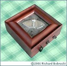
Richard Bobrucki of Newbury, England constructed this beautiful version of the Minimum Theremin in a wood case with an elliptical metal drawer handle for the antenna, reminiscent of 1930s styling. For this theremin, about eight inches of sensing distance was obtained, somewhat less than the nominal 18 inches specified. The reduction is likely a result of the relatively small antenna geometry and its proximity to the circuit board. The theremin's cabinet is approximately 8 inches square.
Jairo Moreno, an exceptional musician from Barcelona, Spain, adapted his Minimum Theremin with a shoulder strap.
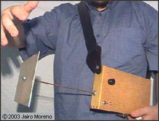
Jairo recorded this fine rendition of "Malvarmo," his adaptation of Eduard
Artemiev's "Russian Theme" from the film "Urga." Malvarmo means "cold" in
Esparanto.
Malvarmo (922KB mp3) |
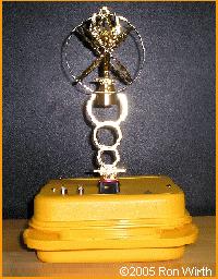
For their Destination ImagiNation® project, team Accck Phttpt built this instrument that combines the Minimum Theremin with elements of Christopher's optical theremin circuits. The team won first place in their regional tournament.
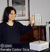
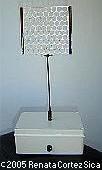
Renata Cortez Sica, a piano instructor from Araras, Brazil, constructed this Minimum Theremin as one of her first electronics projects. See Renata's web page with more information about herself and her interests.
|
|
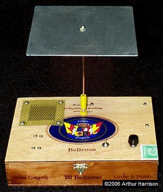
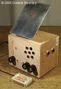
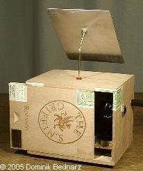
Dominik Bednarz, from Germany, constructed his Minimum Theremin in a cigar box, with an audio amplifier based on the LM386 integrated circuit. The right photo shows the sliding cover of the box, which can be adjusted to set the resonance of the theremin's tone. Dominik also incorporated a photoresistive cell in his design, which serves as proximity-controlled volume modulator. The photoresistive cell is located in the matchbox, seen in the left photo.
|
 |
Raffaello Bisso of Genova, Italy built this Minimum Theremin in a plastic
enclosure with a transparent lid and a disc antenna. He added an LED to provide
a visual indication of zero beat, and reports that the sensing distance is
quite adequate, despite the somewhat-reduced antenna area. Raffaello also
reported that his instrument has no AC noise nor unpleasant sounds, and a
clean output.
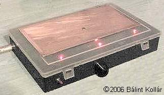
Bálint Kollár of Hungary built a Minimum Theremin in a small plastic tool case. The red LEDs are for decoration, and the antenna is the flat plate attached to the top. Bálint reports a 12 inch sensitivity range, and was "absolutely amazed by the results."
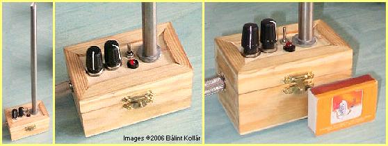
Here is another version of the Minimum Theremin created by Bálint Kollár. He calls it the "Mini Minimum," and it is likely one of the smallest versions of the Minimum Theremin made to date. The image on the right has a matchbox to show the truely miniature size of this instrument. Bálint reports a sensing distance of 10 to 12 inches, and the ability to obtain low-pitched notes, as well.
Felix Obée from Germany adapted this Cookie Monster puppet to incorporate a Minimum Theremin. The theremin's circuit board, an amplifier, and copper plate antenna are in the puppet's tummy, and a small loudspeaker in the mouth produces a tone when a hand is brought near. "Quäk," translated to English, means to mewl (cry softly). The piece was displayed in an art exhibition in Frankfurt. Felix reports, "I worked with various theremin circuits before this one and I found it very reliable." More about Felix's work can be found on his webpage. The Cookie Monster was created by Jim Henson in the 1960s, and featured on the children's television show "Sesame Street."

Kynar® is a registered trademark of Elf Atochem North America, Inc.
Teflon® is a registered trademark of E. I. du Pont de Nemours and
Company.
Wire-Wrap® is a registered trademark of Cooper Industries, Inc.
Destination ImagiNation® is a registered trademark of Destination
ImagiNation, Inc.
Text and drawings ©1999, 2006 by Arthur Harrison