 |
|
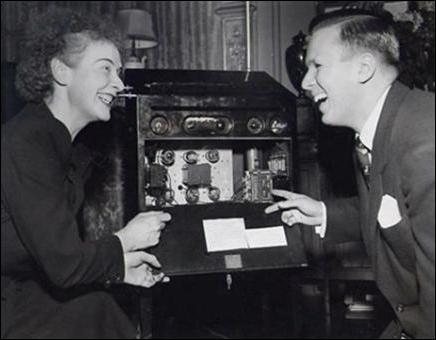
Lucie Rosen's Theremin
|
|
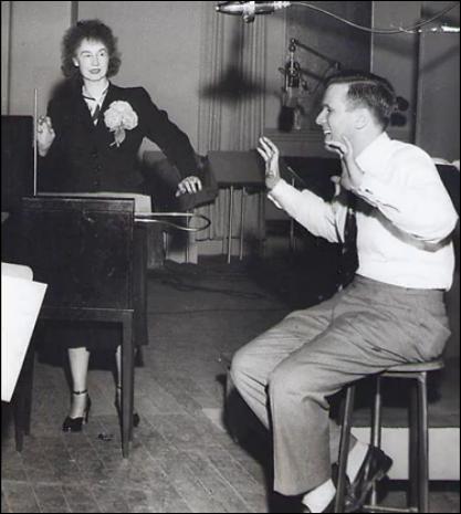
Lucie Rosen with Bandleader Elliot Laurence
Lucie Bigelow Rosen, a benefactor of electronic music development in the 1920s and 1930s, provided financing for Leon Theremin during his decade-long sojourn to the United states from Soviet Russia. Theremin's laboratory was situated in Manhattan, and the Rosen estate, "Caramoor," was not far away, in Katonah, New York. Around 1938, Rosen commissioned Theremin to build at least two known instruments, one refered to as the "January Theremin," and the other, the "September Theremin." The instrument described here is believed to be the September version.
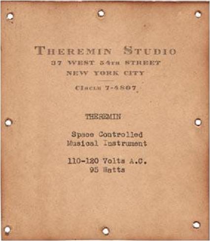
In 2009, I was requested to review a newly-discovered theremin, procured by restoration expert Andrew Baron, in the context of a Public Broadcasting television program, "The History Detectives." The objective was to determine if Baron's theremin was produced in the Manhattan laboratory, by Leon Theremin himself, as would be suggested by a label inside the instrument's cabinet. The episode may be viewed here.
Part of my effort included a trip to the Caramoor estate where some of the episode was taped, and where I examined the Rosen theremin to observe its style of construction, comparing it to Andrew's theremin. There, I met Albert Glinsky, theremin historian and biographer of Leon Theremin, and also a contributor to the History Detectives project. He had examined Rosen's archives, finding documents that included a schematic that appears to match the Rosen September theremin in most details. This schematic, dated May 29, 1946, is initialed "G.G.," for George Gruendel, the "technician in charge of Professor theremin's instruments," according to archive notes. It is speculated, however, that Gruendel only added notations to the schematic, and that it was drawn by Theremin. Two distinct styles of handwriting on the document support this theory.
I used Theremin/Gruendel schematic as a basis for the schematic presented here. Six of the vacuum tubes, V1 through V6. and their associated components, are part of the main assembly, housed in the podium cabinet. Vacuum tubes V7 through V14, and voltage regulator tubes VR1 and VR2 are part of a separate power supply/amplifier assembly. To effect readability, I eliminated the inter-assembly connectors from the schematic, making the signal flow easier to understand. I also rearranged the coils in a logical order, so that the function of the oscillators can be better understood. For the purpose of discussion, I added designations to the components (B1, C1, etc.).
The instrument has two major assemblies, the podium-enclosed pitch and volume chassis (V1 through V6) and the power supply/amplifier chassis (V7 through V14; VR1, and VR2). A separate vintage loudspeaker cabinet was employed during my visit, although the amplifier chassis has fittings that were said to support poles for a diamond-baffled speaker, used with many theremin installations from the period.
The original schematic has volume-control coil L1 and T1's left winding shown as a tapped coil, with no indication of how it couples to the V2 volume oscillator circuit, so I made an assumption that the smaller winding was part of T1. I also made a few assumptions regarding mains wiring and power supply distribution that were cut off the original.
The original schematic only indicates one type 5Z3 dual rectifier, but a notation (probably Gruendel's) indicates "2-5Z3s." I therefore show two paralleled dual rectifier tubes, V13 and V14, in my schematic.
At the conclusion of my visit to Caramoor, everyone involved was excited
about the possibility of activating the September Theremin, but with some
trepidation, since the instrument (which is not fused) had been idle over
a decade. Warren Hammer of Go Production Services was on hand, and
enthusiastically put forth considerable effort to move it to a nearby kitchen,
with a fire extinguisher close by, for testing. To our great satisfaction,
the pitch part of theremin worked, producing almost exactly the seven-octave
range for which it was designed. The volume control did not seem to respond
correctly, perhaps requiring some calibration or repair.
Circuit Description
Power Supply
Transformer T7 converts the AC mains voltage to high voltage for paralleled dual rectifier tubes V13 and V14. A 5V winding provides 6 amperes of filament current for V13 and V14, and a 6.3V winding provides 4.2 amperes of heater current for audio power amplifier tubes V7 through V12. DC high-voltage filtering is provided by capacitors C29 and 30, and inductor L3. They are followed by two 90V in-series voltage regulator tubes, VR1 and VR2. R19 serves as a current limiting ballast for the regulators. The regulated 90V is used for the theremin's three oscillators, and the regulated 180V for the volume circuit. T8 provides a total of 10.75A of heater current for the volume section tubes (V1, V2, V3) and pitch-section tubes (V4, V5, V6). There is no indication of a safety fuse in the source document.
Amplifier
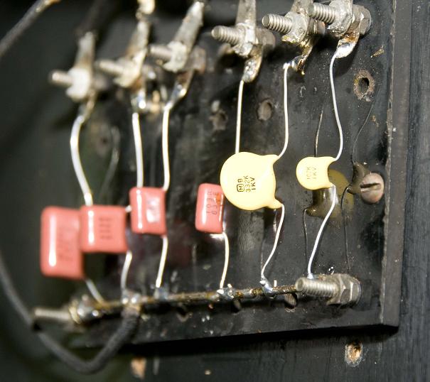
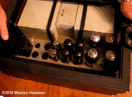
Pentode tubes V7 and V8 are drivers for push-pull beam power tubes V9 through V12. Potentiometers RV1 and RV2 provide amplitude trim for adjusting waveform symmetry. The potentiometer adjustments also influence V7 and V8's DC bias. R17 sets the output tube class-A DC bias. Tone control is provided with an eleven-position rotary switch in the podium cabinet, of which five are used to connect various capacitors directly across output transformer T6's primary. No values for these capacitors are provided in the original schematic, however, physical examination of the instrument revealed some of them, as may be seen in this photograph. The capacitors shown in the photo are not original, and were replaced during a repair by Robert Moog. Here is an image of the amplifier assembly, probably capable of delivering at least 100W of peak power for performances in large rooms such as the concert hall at Caramoor.
Pitch Section
Triode tube V6 and associated components form a resonant Armstrong oscillator that provides a pitch reference frequency. Air-core transformer T4 provides plate-to-grid feedback coupling, and capacitors C14 and C15 provide frequency adjustment. Variable capacitor C15, presumably located on the operating panel, allows the player to adjust zero-beat when the pitch hand at the furthest distance. Resistor R8 provides DC grid bias for V6, and capacitor C13 provides AC bypass.
Triode tube V4 and associated components form a second Armstrong oscillator that provides a variable frequency dependent on pitch hand position. Air-core transformer T3 provides plate-to-grid feedback coupling. Capacitor C11 provides frequency selection. Resistor R5 provides DC grid bias for V4, and capacitor C10 provides AC bypass. Coil L2 has a large inductance, permitting a reactance that is easily affected by small hand-capacitance variations, effecting a greater change on oscillator frequency that would otherwise be obtained if the pitch antenna were directly connected to V4's plate. In addition, the composite response of the two tuned circuits (T3-C11 and L2-Chand) somewhat improve the linearity of hand distance and pitch. Blocking capacitor C9, not a significant part of the tuned circuit, ensures there is no high-voltage DC potential present on the antenna.
Tetrode tube V5 provides the heterodyning function that mixes the waveforms from the two pitch oscillators. Resistor R6, in series with the screen grid, and R7 in series with the control grid, are surmised to provide a degree of tone control by both altering the degree of mutual coupling (through V5) of the two pitch oscillators, and by changing the DC operating point of V5, thereby affecting the heterodyne waveshape. +180 V is provided to V3's plate via T2's primary.
T2's secondary drives triode V3's grid. V3 provides amplification of the tone and drives the power amplifier input via T5's primary. The amplitude of V3's plate waveform is controlled by the amplitude of a DC voltage provided by the V1, V2 volume control section.
T2, prominently branded with the United Transformer Corporation's "UTC" logo, appears to be one of the premium "Linear Standard" highly-shielded types introduced in the 1940s. It may be an early replacement; archive notes mention that a transformer in one of the two Rosen theremins had been replaced, although the notes are not clear as to which theremin it was.
Volume Section
Triode tube V2 and associated components form a third Armstrong oscillator that provides a variable frequency dependent on volume hand position. Air-core transformer T1 provides plate-to-grid feedback coupling between its center and right winding. Capacitors C5 and C7, and variable capacitor C4 provide frequency adjustment. Resistor R3 provides DC grid bias for V2, and capacitor C6 provides AC bypass.
T1's third (left) winding couples the oscillator's output into a resonant circuit comprised of coil L1 and capacitor C2. L1 and C2 provide a hand capacitance-dependent waveform amplitude corresponding to the volume hand's position. L1 has a large inductance, permitting a reactance that is easily affected by small hand-capacitance variations, effecting a greater change on waveform amplitude than would otherwise be obtained if the volume antenna were directly connected to V1's grids. This waveform is applied between the cathodes and grids of dual triode tube V1, which modulates its conductance. (Both sections of V1 are paralleled, so it essentially acts as a single triode.) As V1's conductance varies, so does its cathode voltage, which feeds the plate supply of V3 through its plate load, which is T5's primary. This design is somewhat an innovation compared to Theremin's previous volume circuit designs (e.g., the RCA and Rockmore theremins), since the volume oscillator frequency is not modulated with hand capacitance. Instead, the resonance of the following stage is varied. (Note that some variation in the volume oscillator frequency will likely still occur with hand distance, due to the mutual coupling between T1's windings.)
Battery B1 is inserted in V1's cathode-to-grid circuit to offset the operating range of the tube, presumably allowing its complete cut-off when the volume hand is closest to the antenna. A battery tap at -4.5V is presumed to further ensure volume cut-off, perhaps by offsetting the operating range of V3. Beyond these general assumptions, however, the exact function of the battery is difficult to define without making direct measurements. Sometime in the 1990s, Robert Moog replaced the battery with a line-operated power supply that was evident in the physical theremin.
Discrepancies
Some of the instrument's physical attributes do not match the schematic details.
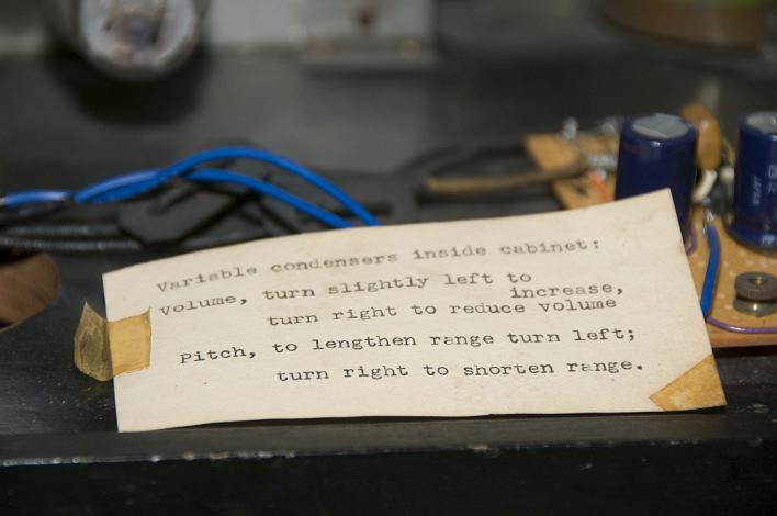
A paper inside the theremin refers
to "variable condensers [capacitors] inside cabinet." However, the only variable
capacitors in the schematic are the ones that have exterior knobs; C4 for
volume and C15 for pitch. There is a short shaft adjacent to the shaft extension
that goes from the chassis to the front panel's pitch knob. This may be the
shaft for one of the variable condensers noted on the paper, perhaps for
pitch calibration. The location of a second calibration capacitor shaft was
not apparent in any of the images.
The physical instrument has a lamp on the top-left of the enclosure that
is presumed to be part of a pitch-indicating circuit. This circuit, according
to Rosen's notes, uses two vacuum tubes, a type 57 and type 58, not in the
schematic.
Rosen's notes refer to a capacitor between V5 pin 2 and V3 pin 3 that is adjusted in value for residual tone (tone that is present with the volume hand closest to the antenna, allowing the player to have a pitch cue). In modern theremin parlance, this is often called "pitch preview," while the historic notes refer to this feature as "audio leakage" and "hum." Such a capacitor is not in the archive schematic.
There is no schematic indication of an AC pilot light, which is present in the physical instrument.
2013 October 27
Text and drawing ©2013 by Arthur Harrison
Back to the Opening Page of Art's Theremin Page