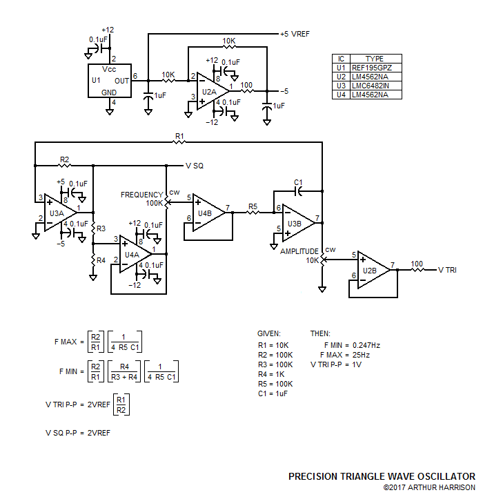
Precision Triangle Wave Oscillator
The circuit illustrated provides
precise low-frequency triangle waves with excellent linearity and
symmetry with parameters that closely follow the equations provided.
U1
is a +5V reference that requires capacitive loading (1uF) for
stability. This capacitance also provides the advantage of excellent
transient response, as well as lowered noise. U2A is a low-noise
operational amplifier configured for a gain of -1, with a 1uF capacitor
providing further noise reduction. The 100 ohm resistor at U2A's output
prevents the capacitor from causing op-amp instability.
The +5
and -5 volt outputs from U1 and U2A provide the supplies for dual
op-amp U3. U3A is configured as a comparator with a reference of 0V at
its negative input. U3B is configured as an integrator. U3 utilizes
CMOS devices, permitting the comparator's lightly-loaded output to
swing essentially to the +5 and -5 volt supply rails, contributing to
waveform symmetry.
Resistors R3 and R4 divide the V SQ voltage
by about 100, driving the input of unity-gain configured U4A. A
resulting square wave with amplitudes of about +0.1 and -0.1 volt
result at U4B's output.
The square waves are applied to the
clockwise and counterclockwise terminals of a 100K potentiometer, the
slider of which drives the input of unity-gain configured op amp U4B.
U4B's output drives the U3B integrator, which exhibits a time constant
determined by R5 and C1. R5 may be a relatively large value, since the
input current of CMOS U3 is very small, preventing any significant
offset voltage.
The output of U3B is fed back to the comparator
section, U3A, through resistor R1, completing the oscillator's positive
feedback loop. Operational amplifier sections U4A and B, while not
strictly necessary for oscillation, provide the advantage of removing
the frequency potentiometer's end-to-end tolerance from the
frequency-determining equation. This permits the use of any
potentiometer, provided that it has a relatively high value to allow
U3A's output to swing close to the rails. An inexpensive ten-turn type
such as Bourns 3590S-2-104L, equipped with a turns-counting dial, would
therefore be suitable for an accurate direct-indication of frequency.
U3B's
output drives an amplitude potentiometer buffered with unity-gain
configured op-amp U2B, permitting the triangle output amplitude to be
set between 0 and 1V P-P.
The values shown provide an
approximate 100:1 frequency range of 0.247Hz to 25Hz. Note that R3 and
R4's ratio may be refined for an attenuation of precisely 100:1 to
obtain a more precise lower value of 0.25Hz (where R3 is made a
non-standard value of 99K ohms).
While the circuit's frequency
may be predicted by the equations at relatively low frequencies,
propagation delays, comparator recovery time, and stray reactance will
degrade that predictability as the integrator's time constant is
lowered. The practical limit of F MAX is about 250Hz, where a measured
-3% deviation from the predicted value occurs.
The oscillator's
frequency range may be conveniently switched in decade bands by
substituting C1 with larger values (to lower the frequency) or smaller
values (to raise the frequency). A metalized polypropylene or similar
low-loss capacitor should be used for C1.
November 9, 2017
Source documents dated October 23, 2017
Text and image ©2017 by Arthur Harrison
Back to the Circuit Library Index
Back to the Opening Page of Art's Theremin Page